This is the PLC program used for alarm indication in process control.
Alarm indication in process control
In many industries, there are many machines that can perform many tasks automatically. Many sensors and components are used in the system or process.
Sometimes operators may not be able to identify machine or system problems through visual observation. And sometimes the machine may stop working due to some problems.
Problem diagram
Problem solutionWe can solve this problem by adding alarms to the system or process. Add an alarm to remind the operator to monitor the machine/process that is about to exceed its limit or has exceeded the limit.
The alarm is indicated to the operator through the annunciator or horn and the lights of different colors on the panel. (For example, green light means normal, yellow means abnormal, and red means bad.)
The purpose of alarms is to use automation to help operators monitor and control the process, and alert them to abnormal conditions in the factory.
The input/input process signal is continuously monitored. If the value of a given signal enters an abnormal state, a visual and/or audio alarm will notify the operator of the situation.
We can configure the alarm for the system in different ways, such as MIMIC, panel indicator, SCADA, HMI, etc.
For our discussion, we considered a simple system and configured alarms for the system.
For example, consider a filling and discharge process. In this system, we have to consider some alarms. We will display the alarms through the lights on the panel.
For example, consider the following alert of our system,
- Emergency stop is pressed
- Inlet valve open error
- Inlet valve closed error
- Drain valve open error
- Drain valve closed error
Here are all errors, so we take all the red indicators shown in the picture above.
Input/output list
Inputs List
- Cycle START : I0.0
- Cycle STOP : I0.1
- Low Level Switch, LL : I0.2
- High Level Switch, LH : I0.3
- Feed VLV open LS : I0.4
- Feed VLV close LS : I0.5
- Disc. VLV open LS : I0.6
- Disc. VLV close LS : I0.7
- Emergency STOP : I1.0
- RESET : I1.1
Output List
- Cycle ON : Q0.0
- Feed valve : Q0.1
- Disc valve : Q0.2
- BUZZER : Q0.3
- Emergency STOP pressed : Q0.4 (Indication lamp)
- Feed VLV open error : Q0.5 (Indication lamp)
- Feed VLV close error : Q0.6 (Indication lamp)
- Disc VLV open error : Q0.7 (Indication lamp)
- Disc VLV close error : Q1.0 (Indication lamp)
PLC Ladder diagram for Alarm indication in Process Control
Procedure description
In this application, we used Siemens S7-300 PLC and TIA Portal software for programming.
Network 1:
In network 1, we use a latch circuit for periodic ON (Q0.0) output. Press cycle START PB (I0.0) and STOP to start by pressing STOP PB (I0.1).
When the cycle starts, the system checks the level of the water tank. If the water tank level is low, the feeding process will start, if the water tank level is high, the unloading cycle will start.
Network 2:
When the water tank reaches the low level, LL (I0.2) will be activated and the feeding cycle will start. Here we take the normally closed contact of LH (I0.3), so when the PLC detects a high level, it will stop the feeding cycle.
Network 3:
When the water tank reaches the high level, LH (I0.3) will be activated and the discharge cycle will start.
Here we have taken the NC contact of LL (I0.2), so when the PLC detects a low level, it will stop the discharge cycle.
Network 4:
When the system receives the emergency stop (I1.0) input, it will activate the emergency stop press output (Q0.4) and provide an alarm indication to the operator.
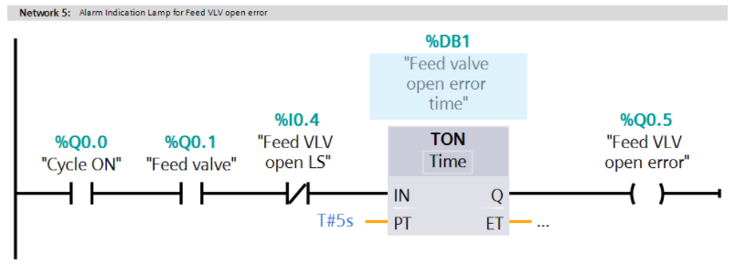
Network 5:
In this network, we have configured the feed VLV open error alarm (Q0.5). When the feed valve is opened and the feed VLV open LS (I0.4) is not detected, the timer will start, and it will enter after 5 seconds. The VLV open error alarm is turned on (Q0.5).
Network 6:
In this network, we have configured the feed VLV CLOSE error alarm (Q0.6). When the feed valve is closed and the feed VLV CLOSE LS (I0.5) is not detected, the timer will start, and it will enter after 5 seconds. The VLV CLOSE error alarm is turned on (Q0.6).
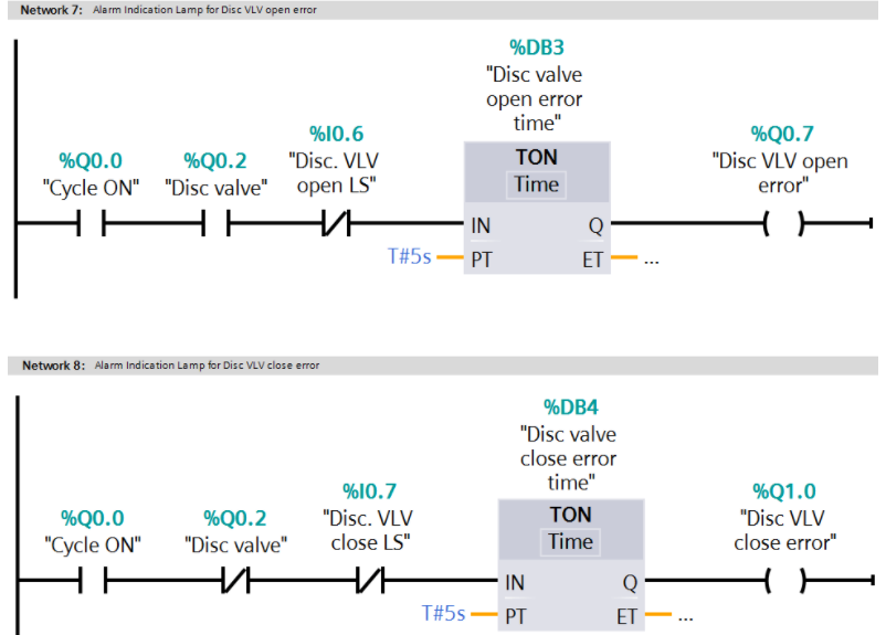
Network 7:
In this network, we have configured Disc VLV OPEN error alarm (Q0.7). When the Disc Valve is opened and Disc VLV OPEN LS (I0.6) is not detected, the timer will start. After 5 seconds, Disc VLV OPEN error The alarm is turned on (Q0.7).
Network 8:
In this network, we have configured Disc VLV CLOSE error alarm (Q1.0). When Disc Valve is CLOSE and disc VLV CLOSE LS (I0.7) is not detected, the timer will start, and Disc VLV close error after 5s The alarm is turned on (Q1.0).
Network 9:
In this network, we have configured buzzers for all alarms. When an alarm is detected, the buzzer (Q0.3) will be activated, and it can be reset by pressing reset (I1.1).
Network 10 :
Operator can reset the BUZZER by pressing RESET (I1.0)
Test Cases
Note: The above PLC logic provides the basic idea of PLC application in process alarm indication. The logic is limited, not a complete application.
For business inquiries, please contact us through our official email:
[email protected]! Have a great time! :)