
The total capacity of a parking lot is for cars. The number of vacancies will be shown on the display outside the parking spaces and the available parking spaces will be indicated by LEDs. This is achieved in the PLC using the Ladder programming language.
PLC program
Here is the PLC program for the car park system, along with the program description and runtime test cases.
List of Inputs and Outputs:
 I:1/0 to I:1/4	= IR Sensor to detect the presence of cars (Inputs)
 O:2/0 to O:2/4	= LEDs to indicate presence of car spots   (Outputs)
 C5:0		= To increment when Car exits		   (Counter Up)
 C5:0		= To decrement when Car enters		   (Counter Down)
 O:6		= Display address			   (Output)
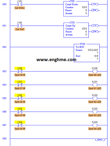
- Counter Up CTU and Counter Down CTD are used to determine the entrance and exit of the car, respectively.
- The value 5 is already stored in the accumulator because there are only 5 parking spaces in this parking zone.
- Therefore, every time a car enters or leaves the parking area, the value in the counter is incremented and decremented accordingly.
- The accumulator holds the decimal value, so this value is sent to the display through a BCD converter, which converts the decimal number to the equivalent binary-coded decimal signal.
- Display receives whatever value the Accumulator holds, expressed in BCD.
- I:1/5 and I:1/6 are the two inputs from the other two IR sensors to detect the entry and exit of the car accordingly.
- Again, both CTU and CTD have the same address in order to change the accumulator value of both counters based on the exit and entry of the car.
- The XIO (normally closed) contact is used here for the IR sensor output, so the LED lights up when the point is empty.
Tags:
LADDER
omron plc
PIC Projects
plc
PLC Programming
PLC Projects
PLC TRAINING
S7-GRAPH
S7-PLCSIM
Siemens