

1.1 Function of a PLC
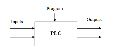
A PLC is a microprocessor-based controller with multiple inputs and outputs. It uses a programmable memory to store instructions and carry out functions to control machines and processes.
The PLC performs the logic functions of relays, timers, counters and sequencers. It has the following advantages:
- Low cost
- Reliability
- Reprogramability
1.2 Inputs and Outputs
The PLC inputs give it information about the machine or process that it is controlling. These are typically switches and sensors. The switches are connected to an input module that provides the interface between the switches or sensors and the PLC.
Input module circuits have opto-isolators to protect the internal PLC circuitry from damage.

The PLC outputs are connected directly or indirectly (e.g. through a relay) to actuator controls. Examples include solenoids on directional control valves, motors, motor contactors, alarms and warning lights.
There are three main types of output module:
Relay (volt-free): The signal from the PLC operates a relay within the output module connecting the control voltage to the output port and hence to the actuator.

Transistor: A transistor is used to switch on the output. This is faster than a relay output but is only suitable for low power direct current applications.
Triac: This solid state device is used for switching alternating current devices. It requires some form of over current protection.
1.3 PLC Architecture and Wiring Diagrams

PLC Connections

PLC wiring diagram