
Hello and Welcome to teckhme.Study and Implementing Finite State Machine Designs in VHDL Using ModelSim.
Finite State Machines is a simple state machine or a fine model of calculation. Each FSM has a finite number of countries, inputs, labors, and rules to change from one state to the other state. FSM is defined by a finite number of countries and switches from one state to the other when specific input is given to the state machine. FSM’s are extensively used in dealing machines, business lights, security cinches, and software algorithms. In this composition, you can learn about the basics of FSM and enforcing an FSM design in VHDL using ModelSim.

What's an FSM?
FSM( Finite State Machine) by the name is defined as a state machine that has a finite number of countries. The illustration for the countries can be A, B, C, and D. Each FSM has input and affair values. These countries keep changing from one to the other when input is given and produces a matching affair.

The green circles indicate the countries of the FSM. So, the available countries are A, B, C, D. The Arrow near the state circle A indicates that ‘ A ’ is the original state. The double circled state, D indicates that D is the last state of the FSM. We can see that arrows are running between the available countries with 1’s and 0’s. These are the inputs and labors that determine where the coming state should shift to and the corresponding labors.
Always flash back that these arrows form the rule for transition. The memos above the arrows left side of the rent represent input, right side to rent represent the affair. For illustration, if it's “1/0 ” 1 represents input, and 0 represents affair.
FSM’s have a state transition table from which we can calculate the coming state. The Transition Table is given below.
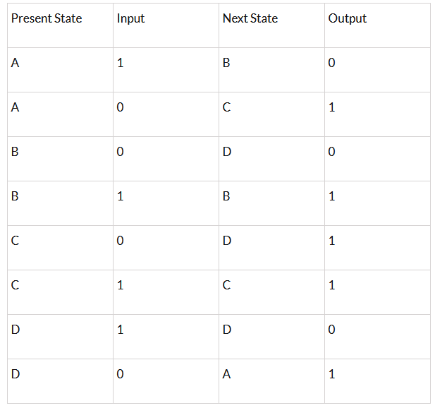
Let us examine the State Transition Table and the State Diagram for a betterunderstanding.However, look for the arrows pointing outwards of state A which has input “ 1 ”, If the present state is A and the input is “ 1 ”. still, the coming state is B and the affair is 0, If so. Now, the present state gets streamlined as “ B ”. Now lookup for the present state “ B ”, says input is 0 the coming state is “ D ”. So on, the state keeps changing.
also, FSM has a timepiece and reset signaltoo.However, it'll go back to the original state which is “ A ”( i, If the reset = 1 or reset isactive.e. starting state)
Now, that we know the basics of FSM, let's apply the same design in VHDL using ModelSim.
Code
library IEEE;

use IEEE.STD_LOGIC_1164.ALL;

entity fsm is

    Port ( reset : in  STD_LOGIC;

           input : in  STD_LOGIC;

           output : out  STD_LOGIC;

           clk : in  STD_LOGIC);

end fsm;

architecture Behavioral of fsm is

type state_available is (A,B,C,D);  --type of state machine.

signal present_state,next_state: state_available;

begin

process (clk,reset)

begin

 if (reset='1') then

  present_state <= A;  --default state on reset.

elsif (rising_edge(clk)) then

  present_state <= next_state;   --state change.

end if;

end process;

process (present_state,input)

begin

  case present_state is

     when A =>        --when current state is "A"

     if(input ='0') then

      output <= '1';

      next_state <= C;

    else

      output <= '0';

      next_state <= B;

     end if;

     when B =>        --when current state is "B"

    if(input ='0') then

      output <= '0';

      next_state <= D;

    else

      output <= '1';

      next_state <= B;

    end if;

    when C =>       --when current state is "C"

    if(input ='0') then

      output <= '1';

      next_state <= D;

    else

      output <= '1';

      next_state <= C;

    end if;

  when D =>         --when current state is "D"

    if(input ='0') then

      output <= '1';

      next_state <= A;

    else

      output <= '0';

      next_state <= D;

    end if;

  end case;

end process;

end Behavioral;
library IEEE;
use IEEE.STD_LOGIC_1164.ALL;
entity fsm is
Port ( reset : in STD_LOGIC;
input : in STD_LOGIC;
output : out STD_LOGIC;
clk : in STD_LOGIC);
end fsm;
architecture Behavioral of fsm is
type state_available is (A,B,C,D); --type of state machine.
signal present_state,next_state: state_available;
begin
process (clk,reset)
begin
if (reset='1') then
present_state <= A; --default state on reset.
elsif (rising_edge(clk)) then
present_state <= next_state; --state change.
end if;
end process;
process (present_state,input)
begin
case present_state is
when A => --when current state is "A"
if(input ='0') then
output <= '1';
next_state <= C;
else
output <= '0';
next_state <= B;
end if;
when B => --when current state is "B"
if(input ='0') then
output <= '0';
next_state <= D;
else
output <= '1';
next_state <= B;
end if;
when C => --when current state is "C"
if(input ='0') then
output <= '1';
next_state <= D;
else
output <= '1';
next_state <= C;
end if;
when D => --when current state is "D"
if(input ='0') then
output <= '1';
next_state <= A;
else
output <= '0';
next_state <= D;
end if;
end case;
end process;
end Behavioral;