
welcome to TECKHME.In this article, you will learn more about Data Logging to Arduino SD Card. We use LM35 temperature sensor to get temperature value and DS3231 module to get time and date. Then we use the SD card module to open the SD card and input the date, time and temperature into the SD card file.

Here are the basic steps to create an Arduino SD card data logger for temperature sensor data:
- Gather materials: You will need an Arduino board, a temperature sensor (such as a TMP36), an SD card shield, and an SD card.
- Connect the temperature sensor: Connect the temperature sensor to the Arduino board according to the sensor's specifications.
- Connect the SD card shield: Connect the SD card shield to the Arduino board according to the shield's instructions.
- Upload the Arduino sketch: You can use the Arduino IDE to upload the following sketch to the Arduino board. This sketch will read the temperature data from the sensor and log it to the SD card.
- Test the data logger: Once the sketch is uploaded, open the Serial Monitor in the Arduino IDE to check that the temperature data is being logged correctly.
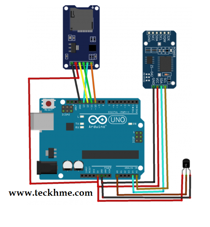
circuit diagram
First, connect the SD card module to the Arduino. The SD card module works with Arduino through SPI communication. The SPI pins on the Arduino are pins 10, 11, 12 and 13.
The connection between OLED and Arduino is as follows:
- Connect CS of SD card module to pin 10 of Arduino
- Connect MOSI of SD card module to pin 11 of Arduino
- Connect MISO of SD card module to pin 12 of Arduino
- Connect the SCK of the SD card module to pin 13 of the Arduino
- Connect VCC of SD card module to Arduino 5V pin
- Connect the GND of the SD card module to the GND pin of the Arduino
After that, connect the DS3231 module to the Arduino. DS3231 module works with Arduino through I2C communication. The pins used for I2C communication on the Arduino are SDA and SCL.
Connect the DS3231 module to the Arduino as follows:
- Connect the GND of the DS3231 to the GND pin on the Arduino
- Connect VCC from DS3231 to Arduino 5V pin
- Connect OLED's SDA to Arduino's A4 pin
- Connect SCL from OLED to Arduino's A5 pin
Finally connect the LM35 sensor to the Arduino. The left pin of LM35 is connected to Arduino's 5V, the middle pin is connected to Arduino's A0, and the left pin is connected to Arduino's ground.
Arduino code:
#include <SD.h>
#include <SPI.h>
#include <DS3231.h>
File sdcard_file;
DS3231  rtc(SDA, SCL);
int CS_pin = 10; // Pin 10 on Arduino Uno
const int sensor_pin = A0;
float temp;
float output;

void setup() {
  Serial.begin(9600);
  pinMode(sensor_pin,INPUT);
  pinMode(CS_pin, OUTPUT);
  rtc.begin();
  // SD Card Initialization
  if (SD.begin())
  {
    Serial.println("SD card is ready to use.");
  } else
  {
    Serial.println("SD card initialization failed");
    return;
  }

  Serial.print("Date  ");
  Serial.print("      ");
  Serial.print("   Time  ");
  Serial.print("     ");
  Serial.print("   Temp   ");
  Serial.println("     ");
  sdcard_file = SD.open("data.txt", FILE_WRITE);
  if (sdcard_file) {
    sdcard_file.print("Date  ");
    sdcard_file.print("      ");
    sdcard_file.print("   Time  ");
    sdcard_file.print("     ");
    sdcard_file.print("   Temp   ");
    sdcard_file.println("     ");
    sdcard_file.close(); // close the file
  }
  // if the file didn't open, print an error:
  else {
    Serial.println("error opening test.txt");
  }
}

void loop() {
  output = analogRead(sensor_pin);
  temp =(output*500)/1023;
  Serial.print(rtc.getDateStr());
  Serial.print("     ");
  Serial.print(rtc.getTimeStr());
  Serial.print("      ");
  Serial.println(temp);

  sdcard_file = SD.open("data.txt", FILE_WRITE);
  if (sdcard_file) {
    sdcard_file.print(rtc.getTimeStr());
    sdcard_file.print("     ");
    sdcard_file.print(rtc.getTimeStr());
    sdcard_file.print("     ");
    sdcard_file.println(temp);
    sdcard_file.close(); // close the file
  }
  // if the file didn't open, print an error:
  else {
    Serial.println("error opening test.txt");
  }
  delay(3000);
}