The Ladder Logic programming language is the leading and most widely used programming language in PLC programming. It is a very intuitive, easy-to-learn, and easy-to-program graphical programming language.
Ladder Basics:
Ladder Logic is a programming language used to program a PLC (Programmable Logic Controller). It is a graphical PLC programming language that expresses logical operations using symbolic notation using ladder diagrams, much like the bars and rungs of a traditional relay logic circuit.
Ladder Logic is a fast and simple way to generate PLC Boolean expressions to automate repetitive machine tasks and sequences. It is used in many industrial automation applications. Some examples of industrial automation applications where PLC ladder logic is used include.
Learn the basics of Ladder Logic
It is relatively easy to learn the basic concepts of ladder logic programming, even if you have no experience with electrical circuits. Take comfort in knowing that ladder logic is the fastest and easiest PLC programming language to learn.
In order to help you learn the basics of ladder logic, we will cover the following….
- Introduction to Ladder Chart.
- Examine the seven basic parts of a ladder diagram.
- Recognize the binary and logical concepts used in ladder logic.
- Automatically detect hidden ladder logic functions included in the ladder diagram structure.
- Discover the five basic logical functions you need to know.
What is Ladder Chart in PLC?
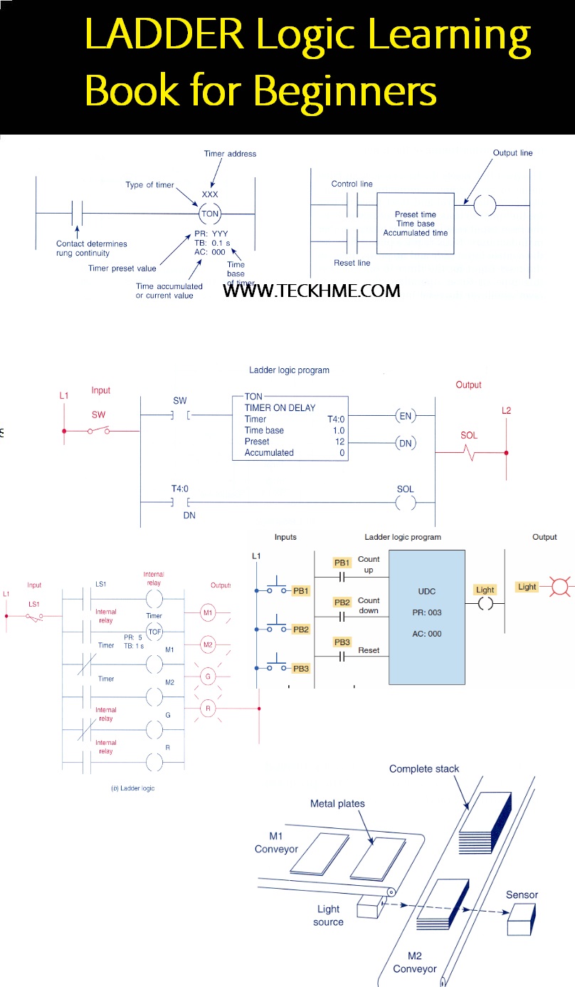
The ladder diagram is the symbolic representation of the control logic used to program the ladder logic for a PLC. Ladder diagrams have horizontal lines of control logic called steps and vertical lines at the beginning and end of each rung called rails. In fact, the structure of the ladder diagram looks like a ladder, hence the name “ladder diagram”.
There are two differences between electrical layout and ladder diagram. The first difference is that the control logic in an electrical diagram is represented using components while ladder diagram symbols are used. The second difference is the implementation of the control logic in the electrical layout as per the operation of the electrical circuit while in the ladder diagram it depends on the systematic nature of PLC scanning.
Why is a ladder diagram used for PLC programming?
The reason ladder diagrams were used for PLC programming is that early control system designers were accustomed to relay logic control circuits and ladder diagrams that closely simulated these circuits. They preferred to use ladder diagrams rather than using text-based programming languages such as C, BASIC, Pascal, and FORTRON. Another reason to use ladder diagrams is that factory maintenance personnel already understand how to read relay control circuits, so using ladder diagrams for PLC programming meant they were easily able to troubleshoot control system problems.
ladder diagrams help you to formulate Boolean expressions into diagrams required for PLC programming. They represent conditional expressions and the input and output as symbols. So writing a PLC program using ladder diagrams is like drawing a relay control circuit.

What is Ladder Chart in PLC?
The ladder diagram is the symbolic representation of the control logic used to program the ladder logic for a PLC. Ladder diagrams have horizontal lines of control logic called steps and vertical lines at the beginning and end of each rung called rails. In fact, the structure of the ladder diagram looks like a ladder, hence the name “ladder diagram”.
There are two differences between electrical layout and ladder diagram. The first difference is that the control logic in an electrical diagram is represented using components while ladder diagram symbols are used. The second difference is the implementation of the control logic in the electrical layout as per the operation of the electrical circuit while in the ladder diagram it depends on the systematic nature of PLC scanning.
Why is a ladder diagram used for PLC programming?
The reason ladder diagrams were used for PLC programming is that early control system designers were accustomed to relay logic control circuits and ladder diagrams that closely simulated these circuits. They preferred to use ladder diagrams rather than using text-based programming languages such as C, BASIC, Pascal, and FORTRON. Another reason to use ladder diagrams is that factory maintenance personnel already understand how to read relay control circuits, so using ladder diagrams for PLC programming meant they were easily able to troubleshoot control system problems.
ladder diagrams help you to formulate Boolean expressions into diagrams required for PLC programming. They represent conditional expressions and the input and output as symbols. So writing a PLC program using ladder diagrams is like drawing a relay control circuit.