
5.Internal relays
These have the same properties as outputs but they only exist in software. They have many uses. Fig below shows an internal relay being used to implement the logic function NAND. This is the inverse of the result of X1 AND X2. We will be making extensive use if internal relays later in the book.

Note: Most PLCs include a function called a Set and Reset or a flip-flop which latches and delatches an output or an internal relay. Throughout this book I use the latch as described in section 2.4, because of the visual resemblance of the ladder rung to the equivalent hard-wire circuit, in which a relay coil is latched on by a normally-open contact connected in parallel with the start button.
6.Timers
The delay-on timer introduces a delay between the start of one event and the start of another.
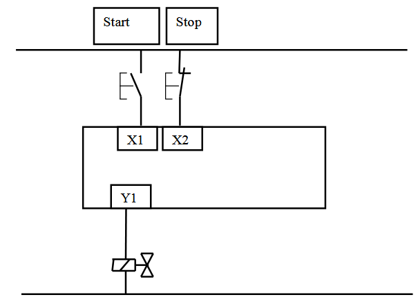
For example, when a start push button is pressed, the pneumatic cylinder shown in Fig below extends, remains extended for 5 seconds and then returns. Draw the PLC wiring diagram and the appropriate ladder logic.


The start button and the end-of-stroke limit switch a+ are the PLC inputs and the solenoid Y1 is the output. Any other components needed for the program can be created in software.

Pressing the start button latches on an internal relay called start_latch. The start_latch relay switches on the output Y1 which energises the solenoid, and the cylinder extends. The cylinder rod closes the limit switch a+ which starts the timer in software. When the timer set value time has elapsed the normally-closed contact Timer_1 in the first line of the program de-energises the Start_latch relay and the cylinder returns.
The timer set value in the TRiLOGI software is in units of 0.1 s. For a 5 s delay a value of 50 is entered in the drop-down menu.

We can do another example using the same hardware with the addition of an alarm as a second output:

When the start push button is pressed and released there is a 5 s delay before the cylinder extends and returns. An alarm sounds during the 5 s delay.

When the start button is pressed the start_latch relay is energised. The Start_latch relay switches on the timer input and the alarm. When the timer set value has elapsed the alarm switches off and the solenoid Y1 is energised. When the cylinder is fully extended the limit switch a+ de-energises the start_latch relay which de-energises the solenoid and resets the timer.
The input to the delay-on timer must remain on for the duration of the timer set value otherwise the timer will not operate. If the signal to start the timer is only momentary then a latch is used to sustain it. When the input to the timer switches off, the timer contacts revert immediately to their normal states. In some PLC models a timer function block can be is located in the centre of a rung as shown in Fig below . When the timer set value has elapsed the timer output switches on allowing a software signal to energise an internal relay coil or an output.
In this book all timer function blocks are located at the right hand side of the ladder diagram and their contacts, normally-open or normally closed, have the same label as the timer.

The delay-off timer causes a delay between its input switching off and its contacts reverting to their normal states. The delay-on timer is used throughout this book.
7.The Pulse Generator
Two counters can be combined to make a pulse generator. This is best illustrated by an example.


Pulse Generator
It can take a while to figure out how the pulse generator works but it is time very well spent. The flow chart in Fig below should help.

Pulse Generator Flowchart
8.Counters
A counter allows a number of occurrences of input signals to be counted. The counter is set to a preset number value and when this value of input pulses has been received, it will operate its contacts. A second input or software coil is provided to reset the current value of the counter to zero.
Consider the cam shaft in Below:

When a start button has been pressed the shaft is to make 10 revolutions and then stop. Pressing the start button also resets the counter. The PLC wiring diagram is shown in Fig Below.


The pulse generator and counter can be combined as shown in this final example.
When a start push button is pressed and held down, an alarm sounds six times before a conveyor starts. Pressing the conveyor stop button also resets the counter. Figs Below show a solution to the problem.

