
In this article we will stady Ladder Programming for begginner.

1.Conditional Logic
The PLC scans its inputs and, depending on the program, switches on or off various combinations of outputs. The logic state of the output depends on the input conditions and so the term conditional logic is used.
A simple example of conditional logic could be stated as follows.
“A machine switches on if either of two start switches are closed and all of three stop switches are closed.”
The conditions could be realised by a hard wire solution as shown in figure below:

The two start switches are connected in parallel. Current will flow if one or the other or both are closed. The start switches are normally open. This means that the contacts are apart and no current flows when the switches are in their normal (or unoperated or rest) state.
The three stop switches are connected in series. Current can only flow if thefirst and the second and the third are closed. The stop switches are normally closed. This means that the contacts are connected and current can flow when the switches are in their normal state.
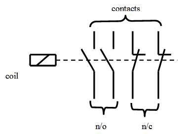
The relay is a switch with multiple contacts that is operated when its coil is energised. The contacts are usually capable of carrying a larger current than push- button or limit switches. Large relays for motor starting are called contactors. The schematic diagram for a typical relay is shown in Fig below:
2.Ladder Diagrams
To realise the conditional logic statement from section 2.1 using ladder logic we connect the switches to a PLC as shown:

To avoid later confusion regarding the concept of normally open (n/o) and normally closed (n/c) it is worth looking again at Fig above and remembering that the plc scans each input and asks “Is it on or is it off?” The five switches shown are external devices and the PLC knows nothing about them. As far as the PLC is concerned, at the moment, inputs X1 and X2 are off and X3, X4 and X5 are on.
I have written the ladder logic using the TriLogi software. (For details of entering program elements see the Appendix)

It can be seen from the Figs above that the output machine will not be energised until one of the inputs Start 1 or Start 2 is switched on.Pushing any of the three Stop switches will turn off the input and so de-energise the output. It is normal practice to use normally closed push-button switches for stop buttons so that a failure of control voltage supply has the same effect as the pressing of the stop button.
3.Normally closed contacts

The contact Start 1 in Fig will be closed when the input is switched off and so the output Machine will be switched on. Switching on the input opens the contact and switches the output off. Remember that the nature (n/o or n/c) of the external switch that turns the input on, has no effect on the ladder logic.
4.Outputs and latches
Output states (on or off) can be used in programs as conditions for other actions.Figure BELOW is the wiring diagram for the program shown in Fig X.

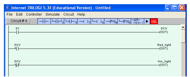
Fig X
Switching on the input S1 switches on the output DCV which in turn switches on the red light. When the output DCV is off the green light is on.
Example :
Write a PLC program to implement the conditional logic statements (a), (b) and (c) below.
(a) A PLC output is to switch on if any of three inputs is switched on.
(b) A PLC output is to switch on if any one of three inputs is switched on but not two or more.
(c) A PLC output is to switch on if any two outputs are switched on, but not the third
Solution:
a)

b)

c)

This program is similar to (b) above.
The push button and limit switches most commonly used in industrial automation are the momentary contact type. A spring action reverts the switch to the normal state as soon as the button or roller is released. These are obviously not the same as the self- latching switches used, for example, in domestic circuits.
The fact that the majority of control switches are not self-latching is not as inconvenient as it sounds. We can easily program in a latch in the ladder diagram.

When the start push button switch in Fig above is pressed, the output Y1 is to switch on and stay on until the stop button is pressed.
When the output Y1 is energised we use a normally open contact of it in parallel with the start button to hold (or latch) it on. The output can only be de-energised by the pressing of the stop button. Note that we have used a normally closed switch as a stop button .

The latch concept can be extended to any number of start and stop switches. The output Y1 in Fig above is to be switched on by X1 or X2 and is to stay on until any of the inputs X3, X4 or X5 is switched off. The required ladder diagram is shown in Fig below.
