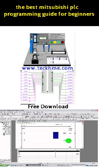
Hello and welcome back to teckhme.today we will present a mitsubishi plc programming guide for beginners.
1) Scope of this manual
This manual gives details on all aspects of operation and programming for FX, FX2C , FX 0N , FX 0S, FX 0, FX 2N and FX 2NC programmable controllers (PLCs). For all information relating to the PLC hardware and installation, refer to the appropriate manual supplied with the unit.
2) How to use this manual
This manual covers all the functions of the highest specification Programmable (Logic) Controller (PLC).
3) FX family
This is a generic term which is often used to describe all Programmable Controllers without identifying individual types of model names.
What is a Programmable Controller?
A Programmable Logic Controller (PLC or programmable controller) is a device that a user can program to perform a series or sequence of events. These events are triggered by stimuli (usually called inputs) received at the PLC or through delayed actions such as time delays or counted occur-rences. Once an event triggers, it actuates in the outside world by switching ON or OFF electronic control gear or the physical actuation of devices. A programmable controller will continually ‘loop’ through its internal ‘user defined’ program waiting for inputs and giving outputs at the programmed specific times.
What do You Need to Program a PLC?
A variety of tools are available to program the Mitsubishi FX family of PLCs. Each of these tools can use and access the instructions and devices listed in this manual for the identified PLC.
CPU version numbers
Over time Mitsubishi adds newer and better features to develop and enhance the products. Because of the nature of PLCs, that can be likened to ‘industrial computers’, changes sometimes occur within the units main CPU (Central Processing Unit). These changes are similar to those experienced by office and home computer users, that is, going to a version up.processor. The following lists identify the CPU versions that had significant upgrades or new functions and features added.
Basic Program Instructions
A program is a connected series of instructions written in a language that the PLC can understand. There are three forms of program format; instruction, ladder and SFC/STL. Not all programming tools can work in all programming forms. Generally hand held programming panels only work with instruction format while most graphic programming tools will work with both instruction and ladder format. Specialist programming software will also allow SFC style programming.
There are six basic programming devices. Each device has its own unique use. To enable quick and easy identification each device is assigned a single reference letter:
- X: This is used to identify all direct, physical inputs to the PLC.
- Y: This is used to identify all direct, physical outputs from the PLC.
- T: This is used to identify a timing device which is contained within the PLC.
- C: This is used to identify a counting device which is contained within the PLC.
- M and S: These are used as internal operation flags within the PLC.
All of the devices mentioned above are known as ‘bit devices’. This is a descriptive title telling the user that these devices only have two states; ON or OFF, 1 or 0.
How to Read Ladder Logic
Ladder logic is very closely associated to basic relay logic. There are both contacts and coils that can be loaded and driven in different configurations. However, the basic principle remains the same.
A coil drives direct outputs of the PLC (ex. a Y device) or drives internal timers, counters or flags (ex. T, C, M and S devices). Each coil has associated contacts. These contacts are available in both “normally open” (NO) and “normally closed” (NC) configurations.
The term “normal(ly)” refers to the status of the contacts when the coil is not energized. Using a relay analogy, when the coil is OFF, a NO contact would have no current flow, that is, a load being supplied through a NO contact would not operate. However, a NC contact would allow current to flow, hence the connected load would be active.
Activating the coil reverses the contact status, that is, the current would flow in a NO contact and a NC contact would inhibit the flow.
Physical inputs to the PLC (X devices) have no programmable coil. These devices may only be used in a contact format (NO and NC types are available)
Example:
Because of the close relay association, ladder logic programs can be read as current flowing from the left vertical line to the right vertical line. This current must pass through a series of contact representations such as X0 and X1 in order to switch the output coil Y0 ON. Therefore, in the example shown, switching X0 ON causes the output Y0 to also switch ON. If however, the limit switch X1 is activates, the output Y0 turns OFF. This is because the connection between the left and the right vertical lines breaks so there is no current flow.
for more information click here to download:


