
hello .in this article we will learn Sequential Programming plc .
1.Introduction
Most machine operations are sequential in nature so it is necessary for the PLC to switch outputs depending not only on the input combinations but also on the current stage in the sequence. An output operating at the wrong time could cause damage or injury so the correct programming technique is critical.
2.A simple automation sequence

The two cylinders A and B in Fig 1 are to go through the sequence
A+ B+ A- B-
Reed switches a-, a+, b- and b+ have been fitted to detect the magnetised cylinder pistons through the aluminium cylinder bodies. The 5 port 2 position directional control valves (5/2 DCVs) are double-solenoid operated.
The PLC wiring diagram is shown in Fig 2

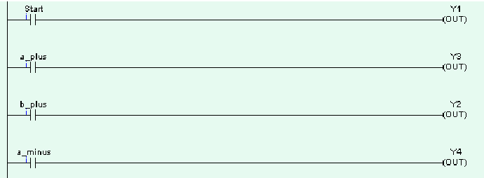
Each event in a sequence is started by the completion of the previous event. When reed switch a+ ,for example, closes, it signals the end of event A+ (the extension of cylinder A) and the beginning of B+ (the extension of cylinder B).
We will write the program line-by-line on this basis.
Pressing the Start button causes the cycle to execute once. The reed switch b- is not required neither is the Stop button
Latching on the Start button with an internal relay and encorporating the reed switch b- causes the cycle to repeat until the Stop button is pressed. This is shown in Fig 4.

It all seems pretty straightforward so far doesn’t it? Let’s try another sequence using the same hardware.

I have entered the ladder logic in a similar way to the first sequence. Everything works fine until we get to the third rung of the program where the reed switch b+ is supposed to energise solenoid Y4 to cause cylinder B to return. At this point both cylinders are extended as shown in Fig 6.

The fact that cylinder A is also extended means that reed switch a+ is closed and therefore solenoid Y3 is energised, cylinder B therefore cannot return. This situation is called a trapped signal. It is characterised by having both solenoids of a double solenoid directional control valve simultaneously energised and it prevents us from programming many circuits in a simple sequential fashion.
The realisation of this sequence is even more difficult using single-solenoid, spring return directional control valves because latching is required and we are still only dealing with a two cylinder problem.
Trapped signals also occur in pneumatics and in electro-pneumatics and various methods are employed to get over the problem. The best known of these is the cascade system but it is only of practical use in simple systems.